
Globe valvesARD-GL-006
Socket weld (SW) connectionCryogenic globe valve
PN320 · SW
A compact PN320 globe-valve reference for socket-weld cryogenic lines. The catalogue lists DN10–25 with a CF8 body; the supplied arrangement drawing covers a different body material.
- Size
- DN 10–25
- Body material
- CF8
- Connections
- Socket weld (SW)
- Operation
- Handwheel
- Pressure
- PN320
- Temperature
- −196 to +80°C · series*
Engineered for your application
A compact PN320 globe-valve reference for socket-weld cryogenic lines. The catalogue lists DN10–25 with a CF8 body; the supplied arrangement drawing covers a different body material.
Sizes and pressure ratings depend on construction, materials and configuration. Confirm the selected pressure-temperature rating with the quotation.
Technical data
The specification, in detail.
| Parameter | Technical specification |
|---|---|
| Size range | DN 10–25 |
| Pressure ratings | PN320 |
| Connection | Socket Weld |
| Operation | Manual handwheel |
| series temperature* | -196°C to +80°C |
| Medium | LNG, LOX, LN2, LAr |
Nominal pressure and ASME class are different rating systems. Confirm the pressure–temperature rating for the selected material and design.
End connections
Define the interface.
Shown configuration: Compact block body, circular bolted bonnet and manual metal T-bar.
| Connection detail | Connection / selection requirement |
|---|---|
| Published connection | Socket Weld |
| Socket interface | Confirm pipe outside diameter, socket bore, depth and wall thickness for the chosen size. SW is not a threaded or butt-weld interface. |
| Reference drawing scope | PN320 supplied socket-weld arrangement, DN15-DN25. Two DN20 body variants are listed. DN10 is not tabulated. Reference body material is S30408; the catalogue CF8 construction needs its own confirmed drawing. |
The illustration shows one configuration. Published connection alternatives are options for enquiry; their availability depends on size, rating, material and design. Installation dimensions come from the drawing, not the illustration.
Materials
From body to seal.
| Component | Material / option |
|---|---|
| Body | CF8 |
| Disc | S30408 |
Supplied reference arrangement
Materials apply to the supplied reference arrangement. PN320 supplied socket-weld arrangement, DN15-DN25. Two DN20 body variants are listed. DN10 is not tabulated. Reference body material is S30408; the catalogue CF8 construction needs its own confirmed drawing.
| Component | Reference arrangement material |
|---|---|
| Hand Lever | S30408 |
| Stem | S30408 |
| Connecting Nut | S30408 |
| Gland Nut | S30408 |
| Connecting Pipe | S30408 |
| Disc | S30408 |
| Gland | S30408 |
| Bushing | HPb59-1 |
| Body | S30408 |
| Gasket | PTFE |
| Bonnet | S30408 |
| Washer | HPb59-1 |
| Gasket | T2 |
Published material alternatives are configuration-dependent. H.F. denotes hard facing; the exact grade and material certificates are confirmed with the offer.
Selection notes
Defined around your application.
- Catalogue body: CF8
- Published connections: Socket Weld
| Engineering data | Configuration requirement |
|---|---|
| Dimension data | Reference table and drawing: DN15, DN20, DN25. Dimensions and connection reference. |
| Installation drawing | Confirm end-to-end length, socket bore/depth, pipe size and wall thickness, overall height and operating/removal clearance. |
| Pressure-temperature rating | Obtain the allowable-pressure table or curve versus temperature for the selected body, seat and seals, including minimum and maximum design temperature. Nominal rating and a family temperature range do not define this curve. |
Sizes and pressure ratings depend on construction, materials and configuration. Confirm the selected pressure-temperature rating with the quotation.
*−196 to +80°C is the series/reference range. It does not establish the allowable pressure at each temperature or suitability of every seat, seal and actuator. Confirm the selected assembly’s minimum design temperature and pressure–temperature curve.
The catalogue operation row says manual handwheel; the supplied image shows a T-bar. The illustration preserves that T-bar arrangement; confirm the operator supplied with the order.
Catalogue construction and supplied reference-arrangement materials are shown separately below the material schedule. Use the approved drawing for the quoted body, trim and connections.
Published ratings do not establish suitability for every listed medium. Oxygen cleaning, material compatibility, trapped-liquid relief and project approvals are specified for the selected assembly. Liquid-hydrogen and helium service require a separate temperature and material review.
Arden product datasheet
Product code ARD-GL-006 · Revision 2026-10-28. Product illustrations show one configuration; the approved order documentation defines the supplied assembly.
Download PDFDimensions
Plan the connection.
Dimensions apply to the tabulated version only. Confirm the approved outline drawing for the selected size, rating and connections before installation.
PN320 supplied socket-weld arrangement, DN15-DN25. Two DN20 body variants are listed. DN10 is not tabulated. Reference body material is S30408; the catalogue CF8 construction needs its own confirmed drawing.
Dimensions and connection reference
| DN | H | A | L | B | D0 | D1 | D2 |
|---|---|---|---|---|---|---|---|
| 15 | 206.5 | 170 | 100 | 12 | Ø15 | Ø22.5 | Ø36 |
| 20 | 206.5 | 170 | 100 | 12 | Ø20 | Ø26 | Ø36 |
| 20 | 286 | 219 | 128 | 12.5 | Ø20 | Ø27.5 | Ø46 |
| 25 | 286 | 219 | 128 | 12.5 | Ø25 | Ø32.5 | Ø46 |
Linear dimensions are in mm and weights in kg unless stated otherwise. Pressure bands in MPa, thread designations and ISO mounting codes are not linear dimensions. Thread designations follow the reference. An em dash means no value is published. Confirm a certified outline drawing for the selected configuration.
Documentation
Product documents
Download the Arden data sheet for ARD-GL-006, or request the outline drawing for your selected configuration.
Product code ARD-GL-006 · Revision 2026-10-28. Illustrations show one configuration; approved order documentation defines the supplied assembly.
Explore the range
Another configuration?
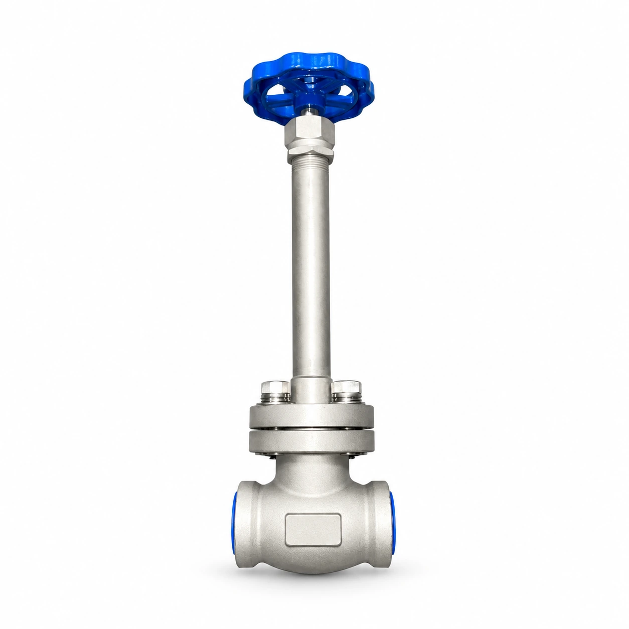 Globe valves
ARD-GL-001
Long-stem globe valve · bolted bonnet
- Size range
- DN 15–50
- Pressure ratings
- PN40 (4.0 MPa nominal)
- Temperature
- −196 to +60°C
- Connections
- Socket weld (SW)
- Medium
- LO2, LN2, LAr, LCO2, LNG
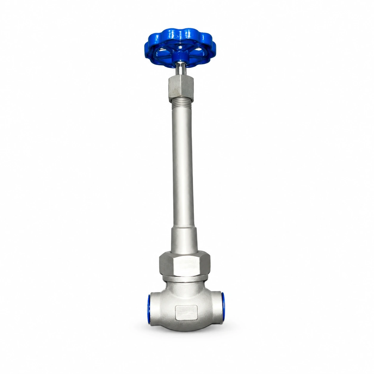 Globe valves
ARD-GL-002
Long-stem globe valve · union bonnet
- Size range
- DN 10–40
- Pressure ratings
- PN40 (4.0 MPa nominal)
- Temperature
- −196 to +60°C
- Connections
- Socket weld (SW)
- Medium
- LO2, LN2, LAr, LCO2
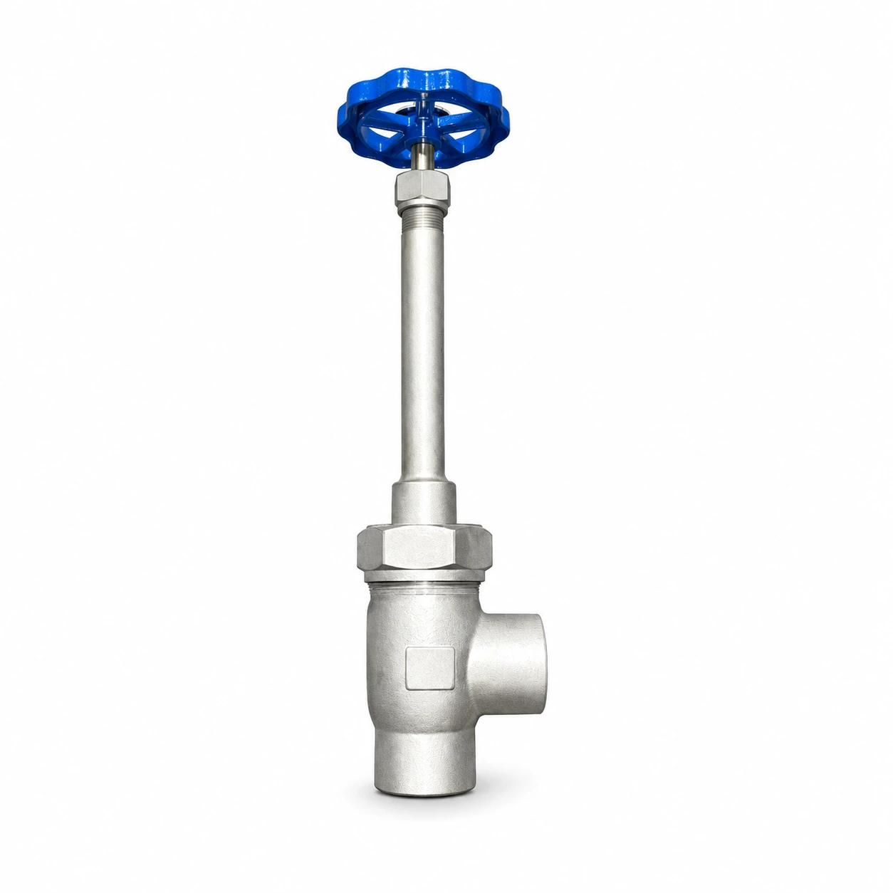 Globe valves
ARD-GL-003
Cryogenic angle globe valve
- Size range
- DN 15-50
- Pressure ratings
- PN16 / PN25 / PN40
- Temperature
- −196 to +60°C
- Connections
- Socket weld (SW)
- Medium
- LO2, LN2, LAr, LCO2